Tutorial: Using AC3D or Blender to export objects into X-Plane
written by: Marko Mamula
Last Updated 31/1/2022
This is a simple guide/ tutorial on how to create, animate and export objects for X-Plane using AC3D or Blender, and import them into X-Plane using Planemaker.
This tutorial uses a side-by-side comparison of the whole process in AC3D and in Blender.
I am an aircraft developer, so everything that I will be talking about relates to exporting for airplanes. It may not work the exact same way for sceneries.
I am only now learning Blender, so I am only documenting what worked for me, there may be other/better/simpler ways to do things.
Please let me know if I can improve anything as I would love to optimize my workflow as much as possible!
I have been using AC3D since the dawn of my development years, and since the official exporter for X-Plane 12 developed by Laminar Research will be developed for Blender only, I am forced to finally learn how to use it myself.
I now have to go through the tutorials and posts online to figure things for myself, I thought it could help others if I documented my learning process and created a simple step-by-step guide that I wish already existed.
Should you use AC3D or Blender?
In short, if it is 2022 and you are just deciding if you should start with AC3D or Blender, DEFINITELY PICK BLENDER.
AC3D
AC3D is a dinosaur of 3D softwares. It’s been around since 1994, and unfortunately, it seems it has not changed that much since then.
Over the years it has been mainly used for creating 3D assets (3D models) for flight simulators, most notably X-Plane. But due to this limited use, it hasn’t been developed into a complex software.
Blender
Blender is a free and open-source 3D computer graphics software toolset used for creating animated films, visual effects, art, 3D printed models, motion graphics, interactive 3D applications, virtual reality, and computer games.
I am amazed to see what people are able to do with Blender. So if you need to invest your time to learn a 3D software, learning Blender makes so much more sense since you can use Blender for so many more things in your life.
However, Blender also has its quirks when creating things for X-Plane, most of which I still need to find though!
AC3D Pros:
It is very straightforward and quite easy to understand, so it is much easier and quicker to learn and use.
As it evolved with X-Plane, everything is set up and created for X-Plane, so there should be no conflicts or issues when exporting.
The X-Plane plugin and exporter is very simple, logical and it “just works” 99% of the time unlike Blender’s exporter.
AC3D Cons:
It is a very primitive software that today in 2022 is lacking some very basic functions that most other modern 3D software have.
Starting with X-Plane 12, Laminar Research will develop the export plugin only for Blender. Meaning that new features that may be required for XP12 may not be available in the AC3D exporter for some time, if ever.
It is expensive relative to the limited functionalities of the software.
Due to its very limited use, there are very few learning materials, tutorials, and videos online for you to learn from.
BLENDER Pros:
It’s free
The official X-Plane exporter developed by Lamiar Research will be developed only for Blender
Much more powerful, you can do many more things than just model and export to X-Plane
BLENDER Cons:
Considerably more complicated to learn and use, especially for someone who has never used any 3D software before
The workflow to export for X-Plane also seems a lot more complicated for some things that are very simple in AC3D
TUTORIAL START
summary
You will use AC3D or Blender to create our 3D models. You will then export those in the x-plane OBJ format , so that you can import them to Planemaker and attach them to an aircraft for X-Plane.
You will also learn the important steps to make the PBR materials properties (Normals, roughness, metallic) appear correct in X-Plane.
0. Preparation
DOWNLOAD PROJECT FILES
First, download the project files below, which contain some files you will need.
Unzip the folder onto your desktop (or wherever you want) and leave it there.
Software versions used:
AC3D 8.3.30
Blender 3.0
Plugins used:
X-Plane Plugins for AC3D 3.5b1
XPlane2Blender v4.0.0-rc.1
Installing X-Plane plugins
You will need to install the X-Plane plugins for both AC3D and Blender.
Here is a link to the AC3D version. I am using the latest version (3.5b1) of the plugin in AC3D 8.3.30 and it works fine, even though it says it should only work in AC3D 8.5+.
Here is a link to the Blender version.
1. Creating a cube
AC3D
1. Open AC3D
2. Go to File > Save as XP AC3D EXPORT TEST.ac
3. Click on the cube in the Mode section, and then click anywhere in the viewport. This will create a cube.
4. While the cube is selected, click on the Move to button, since the numbers there for X Y and Z are just zeros, it will place the cube directly into the origin.
Tip: Hitting Space while you hover over one of the viewports maximizes that viewport to the full screen.
BLENDER
1. Open Blender.
2. Go to File > Save as XP BLENDER EXPORT TEST.blend
3. There will already be a cube in the middle of your viewport. Select it and delete it. Also delete the light and camera in the scene as we won’t need those.
4. To create your own beautifully unique cube, with your mouse in the viewport click SHIFT + A > Mesh > Cube
You should now have a cube in the origin.
5. Let’s scale it down. While the cube is selected, and with the cursor in the viewport, hit N. A properties window is going to show up on the right side. Under Dimensions, change X, Y and Z to 1m.
6. Save your file! You can check my version Blender_Checkpoint_1.blend
2. Creating groups/ collections
In any 3D software, it is essential to organize your objects using the hierarchy. In our case, it will be particularly important because the final exports will depend on it.
When exporting to X-Plane, you will want to divide your objects into sections of the plane that will all share one texture.
For example, the fuselage and all objects related to it will usually all share one texture, let’s call it fuselage.dds. This will also be exported as one obj file, let’s call it FUSELAGE.obj.
The wings could then share another texture of their own, so they need to be exported as a separate obj file. Let’s call the texture wings.dds, and the obj could be called WINGS.obj.
In order to tell the xplane plugins which objects should be exported in which obj file, we need to organize everything into Groups in AC3D or Root Collections in Blender.
AC3D
Technically, AC3D will export objects even if they are not in groups. But because later on, it makes it much simpler to keep things organized, we will put this cube in a group as well.
AC3D only allows you to group two or more objects, so let’s cheat it a bit, and copy our cube in order to make a second one.
1. Select our cube in the Object Select mode (hit ”o” on your keyboard)
2. Ctrl+C, Ctrl+V > This will create a copy of our cube in the same exact position, so you will see them over eachother.
3. The second cube has automatically been selected, so simply drag it out in any direction so that we can see them both.
4. Hit F8 on your keyboard, or Tools > Hierarchy view. This will open the Hierarchy window which lists all your objects. You will see two boxes there.
5. Putting the boxes in groups:
Select both boxes by clicking on them in the Hierarchy view and hit CTRL + G. This will put them in a group.
You could also click on the Group button on top of the Hierarchy view, but only if you are in Group Select Mode
6. Renaming the group: (this also works for renaming objects)
Option 1) In the viewport:
Enter the Group Select mode (hit “g” on your keyboard), and then click on either of the boxes in the viewport or in the hierarchy view.
Once the group is selected, you can rename it in the left side panel under Object Name.
Here change “group” to “Test Cube Group” (or whatever you want).
Option 2) Through the Object Name/Data window
In more complicated setups, you will have groups inside other groups. If you have a group_B inside of group_A, you won’t be able to rename group_B using Option 1), because the Object Name window will always display the first group (parent one) of the hierarchy, so that is why I am mentioning this Option 2) as well.
Right-click on the group in the Hierarchy view > Edit Name/Data.
The Object Name/Data window will appear.
Here change “group” to “Test Cube Group” (or whatever you want)
7. Now that our cubes are in the group, let’s delete the second one we created. Simply select it in Object Select mode, and hit DEL.
8. Save your file!
BLENDER
If you look in the outliner, you should see that the cube should already be inside a Collection.
1. Rename the Collection to Test Cube Collection (or whatever you want)
It is not enough for objects to be inside a Collection for them to be exported, it needs to be defined as a Root Collection.
2. Navigate to Scene Properties > X-Plane
3. You will see that there is nothing under the Root Collections, that is because we didn’t define any Collection to be a Root Collection yet.
4. Click on ▶ Other Collections.
5. You will see the Test Cube Collection listed there. Tick the Root Collection
6. This will now move it to the Root Collections section right above, and it will also now mean that our cube will be exported as a separate obj.
7. Expand the Root Collection settings by clicking on ▶.
Here is where we will define the name of the final obj file, as well as the textures it will be using.
8. Name: TEST CUBE BLENDER
9. Save your file! You can check my version Blender_Checkpoint_2.blend
3. How to assign a texture
For simplicity, we will use textures from the default Cessna Skyhawk.
Note: DDS files are image files. In X-Plane you can use either PNG or DDS format, however, DDS is preferred as it has performance advantages. Click here to learn more about the DDS format.
AC3D
1. Select the cube (make sure the Select mode is on Object)
2. Then click on Object > Texture > Load Texture > navigate to …\X-Plane 11\Aircraft\Laminar Research\Cessna 172SP\objects and select fuselage.dds
3. The cube should now look like this:
This is the texture that will also be exported in the final OBJ file.
4. Save your file!
BLENDER
In Blender, things aren’t as simple. Normally you add textures by defining them in a material which is then assigned to your model. However, the xplane2blender plugin will not export these.
Instead, we will have to define the textures on the Root Collection X-Plane settings.
You should still add the textures to the blender material, in order to see them in the Blender viewport. I will go through all of this below.
1. Select the cube
2. Go to Material Properties (of the object, not the world!) and click on + New
3. Rename Material.001 to Fuselage (or anything you want)
Again, adding textures in the next steps is just so that we can see the textures in Blender. But these textures will not be exported to XP!
4. Left mouse button click (LMB ) on the Base Color Yellow Dot > Image Texture
5. Click on Open and open ..\X-Plane 11\Aircraft\Laminar Research\Cessna 172SP\objects\fuselage.dds
6. Then change the Viewport Shading to Material Preview. You should now see the texture on the cube.
7. Now, in order to actually tell the xplane2blender plugin what textures to export, we need to define that in the Scene X-Plane properties
8. Under the Textures section, we will define the textures that will be written into the final exported obj files.
Important: We do not need to provide a path to the textures, but only the name of the texture file!
9. Open file explorer and go to ..\X-Plane 11\Aircraft\Laminar Research\Cessna 172SP\objects
Locate the textures we want to use, Fuselage.dds and write that file name into the Textures sections.
10. Save your file! You can check my version Blender Checkpoint 4.blend
4. How to export OBJ files for Planemaker/X-Plane
AC3D
In AC3D, you have to export every single obj individually. You cannot export Fuselage.obj and Wings.obj at the same time.
You will define the name of the final obj file every time you export.
BLENDER
When you export your files, all the Root Collections that are visible in the viewport will be exported.
SELECTING WHICH GROUPS GET EXPORTED
In the Hierarchy you can also Hide any object by clicking on the eye icon or Lock it by clicking on the lock icon.
Hiding it will hide it, Locking it will show it as a wireframe only and you won’t be able to select it.
Both hiding or locking will prevent this group to be exported.
SELECTING WHICH ROOT COLLECTIONS GET EXPORTED
1. All the visible Collections get exported.1.
2. If you want to prevent a collection from being exported, simply hide them or exclude them from the viewer, by clicking on the Tick or the Eye icons in the hierarchy.
EXPORTING FROM AC3D
1. Go to File > Export > X-Plane 8 Object File (.obj)
2. Set the export destination to …\X-Plane 11\Aircraft\Laminar Research\Cessna 172SP\objects
3. Set the export name to TEST CUBE AC3D.obj
When you’ll have more groups, make sure that only one group is visible and all the other ones are hidden or locked when exporting.
EXPORTING FROM BLENDER
Option 1)
1. To export, go to File > Export > X-Plane Object (.obj)
2. Set the export destination to …\X-Plane 11\Aircraft\Laminar Research\Cessna 172SP\objects
3. No need to change the default export name as the name of the final OBJ has been previously defined in the Scene Root Collection Properties
Option 2)
You could also click on the Export OBJs on top of the Scene X-Plane Properties (where you defined the name and textures), however you cannot save where the OBJs will be exported, it will always be exported exactly where your .blend file has been saved.
Examining the exported OBJs
Let’s make sure that the OBJs got exported the right way.
Go to the export folder (…\X-Plane 11\Aircraft\Laminar Research\Cessna 172SP\objects) and open the TEST CUBE AC3D.obj / TEST CUBE BLENDER.obj in a text editor.
What we want to see is the TEXTURE fuselage.dds line, which means this object will load the right texture.
AC3D
BLENDER
5. Importing the OBJ files into Planemaker
1. Open Planemaker.exe from the X-Plane root folder
2. File > Open > C:\X-Plane 11\Aircraft\Laminar Research\Cessna 172SP\Cessna_172SP.acf
3. Go to Standard > Misc Objects
4. On the bottom of the screen, click on Add
5. Scroll all the way down, you will find a new undefined object attached
6. Click on the little square next to the empty space, go to …\X-Plane 11\Aircraft\Laminar Research\Cessna 172SP\objects and select TEST CUBE AC3D.obj or TEST CUBE BLENDER.obj, depending on which software you used.
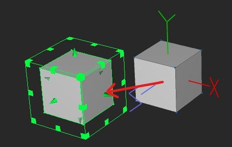
I added both, just to demonstrate for both cases.
7. Change the location based on the numbers below. AC3D cube is on -6 on the Y axis , and Blender cube is +6 on the Y axis.

8. Close this section and you will immediately see that the cube should now be attached to the plane.
9. File > Save
10. Open X-Plane and load the Cessna Skyhawk on an airport ideally where you do not have any scenery installed so that you will be surrounded by water only. This will increase the speed at which X-Plane will be loading and reloading because you will be doing it a lot.
11. We should now see our cube/cubes attached to the plane

6. Using PBR materials in X-Plane
Alongside textures, you also need to assign certain properties to the objects, otherwise, they will not look right. I’ve actually learned a few things myself while trying to make sure this tutorial explains things correctly!
Note: For the purpose of this tutorial, I will simply show you what you need to do, not why you need to do it.
I’m not gonna go into details and theory of PBR (Physically Based Rendering) materials because it’s a very complex topic and others have covered it well. So I advise you to read the following articles if you want to understand what you’ll be doing.
6.1 How to enable Normal maps in X-Plane
This is actually pretty straightforward. Once you have the normal texture created, we just need to make sure that the plugins exports the TEXTURE_NORMAL line in the header.
Some people online mention opening the exported file in a text editor and adding this line of text manually.
This is possible, but please do not ever edit the OBJs manually.
This is a wrong workflow, because your changes will get overwritten every time you export. If you have everything set up correctly, you should not ever need to do it.
AC3D
1. Go to X-Plane > X-Plane Export Settings
2. Tick Export TEXTURE_NORMAL lines
If you cant see that setting, you may need to get the latest AC3D X-Plane plugin.
3. The plugin will assign the same name as the main texture + a suffix “_normal.png”. This means that you need to have your normal map textures end in that, or else it won’t find the texture.
4. The Cessna’s fuselage normal texture is called fuselage_NRM.png. So in order for our object to be able to find it, we need to make a copy of that texture file, and rename it to fuselage_normal.png
Blender
The exporter will automatically write out this line if we define the Normal texture name in the Root Collection > Textures dialog.
We have already defined the fuselage.dds as the color texture in step 3, so now we just need to repeat that with the normal texture.
Open file explorer and go to ..\X-Plane 11\Aircraft\Laminar Research\Cessna 172SP\objects and locate the normal texture we want to use fuselage_NRM.png
Go to the Scene Properties > X-Plane > Root Collections > Textures
In the Normal/Specular field, write fuselage_NRM.png
Let’s check if that worked straight away
Export the cube again
In X-Plane reload the airplane by going to Developer > Reload the current Aircraft and Art (I have this assigned to F11 on my keyboard)
If you zoom in onto the cubes in X-Plane, they should now show the details of the normal map, like the rivets. If you can’t see them very well, try changing the time of the day to sunset, as the details should react to light change.
And after examining the exported files in a text editor, we should now see the TEXTURE NORMAL line written out in the header as well.
AC3D
blender
6.2 How to make objects shiny/reflective and metallic in X-Plane
In other words, how to make sure the specular and metallic channels are being applied correctly.
First of all, this is after you’ve already created a normal texture that contains the specular map in the alpha channel and the metallic map in it’s blue channel. Read more about that in the links above.
Substance Painter does this automatically when using the X-Plane Export config.
In a nutshell, we want to add two magical lines to the header of the OBJs:
NORMAL_METALNESS GLOBAL_specular 1NORMAL_METALNESS
Adding NORMAL_METALLNESS to the header will enable the rendering of metallic surfaces in X-Plane.
The AC3D plugin always seems to export that line by default.
GLOBAL_specular 1
Adding GLOBAL_specular 1.0 to the header of the OBJ file will make all exported objects 100% shiny (or in other words 0% rough). This can further be adjusted with normal maps that include specular maps in the blue channel.
This is really nicely explained in the first link I shared above.
AC3D
NORMAL_METALNESS seems to be added automatically using the latest AC3D plugin (3.5b1). Please correct me if I’m wrong, but I always get that line when I export from AC3D.
There are two ways to add GLOBAL_specular 1 in AC3D:
Option 1) The simple way
(This will require you to have the latest version (3.5b1) of the X-Plane plugin for AC3D)
Steps:
Go to X-Plane > X-Plane Export Settings
In the OBJ file header, write “GLOBAL_specular 1.0”
That’s all!
Option 2) The complicated way
You can use this in case you cannot use the latest plugin and you cannot automatically add the GLOBAL_specular 1.0 line to the header.
You will have to use AC3D materials, and use them to add specularity on a per-object basis, so you will not see the line in the header, but you will see the same result.
1. To check which material is assigned to your objects, go to the Select Surfaces mode (S on the keyboard) and click on one polygon on the object you want to check.
2. When we click on one side of our cube, the info on the bottom bar in AC3D tells us which material is assigned to it:
BLENDER
Both the lines above are added in one single step:
With the cube selected, go to the Material properties
Scroll down to X-Plane
Tick Normal Metalness
What this does is it will write out two additional lines in the header:
These will
That’s it!
In my tests, changing the specular and roughness values on the Blender shader did not have any effect on the final exported OBJ, so you can leave those values all at default.
Although the xplane2blender documentation says that specular is one of the values exported and read by X-Plane, but the screenshots seams to be a bit dated so it is a bit confusing.

3. We can see that the index is 1. You can find all the materials in the Palette tab on the bottom of the left side menus:
The materials in AC3D don’t really give us many options. The only things that will affect the final look in X-Plane are the Diffuse, Specular and Emission.
4. We can edit the first material, however from experience I found that the default materials often reverse the values to default, so it is better to Append a new material:
Right-click on any of the materials in the Palette and click on Append new material.
Go to the end of the line of materials, and you should now see the 15th material.
Right-click on it again, and click Edit Material
DIFFUSE
Always leave it white. If you made it red, all your textures would turn out to be red too.
EMISSION
Using Emission on the whole object would not be practical so just forget it and always leave it black. Later on, we will use textures to enable LIT effects on the cube.
SPECULAR
In order to see the surfaces shiny in X-Plane, we need to make sure the specular value of the material is 1.0 (full white).
Click on the + next to the Specular and drag all three sliders to the right. This will give the specular channel a global value of 1.0.
Note: The “Shininess” only affects the look inside AC3D, it does not affect the final XP look in any way.
I bet that at this point you’d wonder why the hell would anyone use this method when the first one was done in two steps! Well I used to do all of this until today, when I relized that using the AC3D materials is not necessary if the “GLOBAL_specular 1.0” variable is defined. So I learned something today too!
5. Anyway, let’s now make sure this material is actually assigned to our cube and that X-Plane will recognize it:
Select the cube in the Object Select mode
Then simply click on the 15th material in the Palette and it will be assigned to our cube.
On the top bar, go to X-Plane > X-Plane Object Properties
Under Surface: tick Use AC3D Materials.
Note: If you are using this method, you will have to set this setting for all of your objects! You can select all of your objects, then tick Apply to All on the bottom of the X-Plane Object Properties window and then tick “Use AC3D Materials”. It is good practice to uncheck the Apply to All after doing this so that you don’t forget that it stayed on later.
Let’s check if that worked
Reexport your cube
Reload aircraft in X-Plane
The cubes should now also be shiny
7. Single sided polygons
On the picture above where we selected one face of the cube, we can also see that the last thing the info line says is “2S”. That means that our polygons are all double-sided.
Generally, to improve performance, we want to make sure that we always use one-sided polygons on our objects. Only use double-sided polygons if you really need two-sided polygons (e.g. trees, where both sides are visible all the time.)
AC3D
To make your objects single-sided, simply select the whole object, (or all objects) in the Object Select mode, and then click on 1S on the Set Surface Type tab:
blender
Blender seems to export surfaces as single sided by default, so I didn’t do anything here.
Animating the Cube
The cube will rotate based on a dataref. Datarefs are links or references to values that X-Plane writes out every frame. These mostly numerical values drive the animations of our objects.
How to import in planemaker
LIT TEXTURES:
In order to export the _LIT line, I need to either make something a dynamic LIT or export a material that has emission more than zero.
2. Creating a cylinder
AC3D
1. In the same way, we will create a cylinder. In the Mode section, click on the cylinder.
2. Then in the Cylinder section select 24 segments. If you cannot see the Cylinder section, or any other section, just click on the lines between sections and drag them down.
3. Again, place it in the viewport.
4. In the Utils section, write [2.0 , 0, 0] in the first three windows and hit Move to. This is where you can define a position and move it there.
5. The next three windows define the size. Set it to [ 0.2, 0.8, 0.8] and hit Size to.
Blender
3. Importing a carrot
AC3D
File > import > Navigate to the folder you downloaded and unzipped, go to 3D models and select Carrot.obj.
The carrot was placed into the origin, but since we already have a cube in our origin, it is hidden inside. You can see the green handles through the cube though, indicating that it is still selected.
You can also hit W on your keyboard, which will toggle the wireframe view on and off.
On top of the window, click on 200%. That will double the size of the carrot. Click on that three more times so that the carrot becomes bigger than the cube.
We also want to rotate the carrot so that it is vertical. Under the Scale button in the Utils section, select the Z axis, and hit the minus sign. This will rotate the carrot.

After that, drag it directly up in the viewport to get it above the cube.
Blender
Then do the same for the cylinder, but instead of cockpit.dds, use wings.dds.
You will notice that the sides of the cylinder are black. That is because the cylinder object does not have UVs defined on the caps (one of the weird things AC3D does).
You will need to go to the Select Surface mode, and then select only the side polygons of the cylinder.
Then hit F10 to open the Texture Coordinate Editor (basically the UV editor) or Tools > Texture Coordinate Editor and click on Remap > Left
For the carrot, select the texture in the unzipped folder.